🚨 Note: This is not the final version of TSS 2026 but has most functional capabilities of the final version. More information can be found under documents/updates/. 🚨
NASA Spacesuit User Interface Technologies for Students (SUITS) is a design challenge in which college students from across the country help design user interface solutions for future spaceflight needs. The following is a web interface for the SUITS telemetry stream server designed and developed for the challenge.

TSS (telemetry stream server) is the centralized server for sending and receiving data for the challenge. All data from the lunar simulator is sent to TSS, and any commands to control the pressurized rover, or fetch data will be sent to TSS. The following document will detail how you can run your own instance of the server and begin developing your software and hardware.
- Mission Description
- Acronym List
- Rock Yard and DUST Maps
- Rock Yard 3D Scans
- EVA Telemetry Ranges
- Rover Telemetry Ranges
- Clone the repository:
git clone https://github.com/SUITS-Techteam/TSS2026.git
-
Navigate into the root of the repository on your terminal of choice
-
Allow the build script to be ran as an executable:
chmod +x ./build.bat
- To build the server, run:
./build.bat
NOTE: TSS only runs on UNIX based operating systems. If running on Windows, you will have to setup WSL and MUST install GCC. If you don't, several errors will be displayed when trying to build the server.
- To start the server, run:
./server.exe
You should see the following lines in your terminal appear:
Launching Server at IP: 172.20.182.43:14141
Configuring Local Address...
Creating HTTP Socket...
Binding HTTP Socket...
Listening to HTTP Socket...
Creating UDP Socket...
Binding UDP Socket...
Listening to UDP Socket...
Backend and simulation engine initialized successfully
- Type the IP address printed in the first output for
Launching Server at IP: xxx.xx.xxx.xx:14141. This will open the website for the server. From this website, you can interact with the server. This is where you can monitor the state of the simulation, verify the display of your system, and virtually interact with the EVA devices like you will be using during test week.

The devices listed below are physical devices that will be used during test week to create a realistic scenario for both the EVA and rover teams. The sensor data listed below will be synced with the telemetry server and can be fetched for use within your interface.
The umbilical interface assembly (UIA) is a component used at the beginning of an EVA to transfer power and fluids to the suit.

| Sensor | Value True | Value False | Description |
|---|---|---|---|
| EMU1 POWER | ON | OFF | Remotely powers the suit for EVA 1 |
| EV1 SUPPLY | OPEN | CLOSED | Fills EVA 1's liquid coolant |
| EV1 WASTE | OPEN | CLOSED | Flushes EVA 1's liquid coolant |
| EV1 OXYGEN | OPEN | CLOSED | Fills EVA 1's oxygen tanks |
| EMU2 POWER | ON | OFF | Remotely powers the suit for EVA 2 |
| EV2 SUPPLY | OPEN | CLOSED | Fills EVA 2's liquid coolant |
| EV2 WASTE | OPEN | CLOSED | Flushes EVA 2's liquid coolant |
| EV2 OXYGEN | OPEN | CLOSED | Fills EVA 2's oxygen tanks |
| O2 Vent | OPEN | CLOSED | Flushes both EVAs oxygen tanks |
| DEPRESS PUMP | ON | OFF | Pressurizes both EVA suits |
The display and control unit (DCU) used for this challenge is a component that allows the user to control various settings of their suit's operation during an EVA. For example, if scrubber A's CO2 storage fills up, you could flip a switch on the DCU to flush it while switching to scrubber B.


| Sensor | Value True | Value False | Description |
|---|---|---|---|
| BATTERY | SUIT BATT | UMBILICAL POWER | Describes if the suit is running off its local battery or UIA power |
| OXYGEN | PRI TANK | SEC TANK | Describes if the suit is pulling from primary or secondary oxygen tanks |
| BATTERY | PRI BATT | SEC BATT | Describes if the suit is connected to primary or secondary battery |
| FAN | PRI FAN | SEC FAN | Describes if the suit is using the primary fan or secondary fan |
| PUMP | OPEN | CLOSED | Describes if the coolant pump for the suit is open or closed (allows water to be flushed or supplied) |
| CO2 | Scrubber A | Scrubber B | Describes which scrubber is currently filling with CO2 (other is venting) |
NASA SUITS aims to have a physical activity box with various panels and mock sensors for the EV to troubleshoot and repair. This physical box is representative of the Lunar Terrain Vehicle (LTV) External Control Panel and will be referred to as the LTV Task Board. Each item within the LTV Task Board will have a unique procedure for troubleshooting and repair. These procedures may be found in documents/procedures/ltv-repair-procedures.pdf.
Later on, we intend to release high definitions pictures of the LTV Task Board for teams pursuing computer vision solutions.

DUST (Digital Lunar Exploration Sites Unreal Simulation Tool) is a 3D visualization of the Lunar South Pole built in Unreal Engine. Since we can not use a physical rover to drive around in during test week, you will use this software developed by NASA to simulate a pressurized rover.
After being selected as a team to participate in the rover segment of the NASA SUITS challenge, your team lead will be contacted via email with additional instructions to request access to the software. Please note that if your team was selected for the EVA segment of the challenge, you will not need to use this software.

After opening the simulator on a Windows PC, a screen prompting you to enter an IP address will show up. This is prompting you to enter the website address for the TSS server, which is used to communicate back and forth with the simulator. Type in the network address without the port number. For example, if your instance of TSS is running on 172.20.182.43:14141, then you will type in 172.20.182.43. Note that you will want the server to be running on the same network or computer as the device running DUST so that they can commmunciate with each other.
During the challenge, you will be expected to issue commands to control the rover via TSS (see rover commanding). However for debugging purposes, we have included a couple keyboard shortcuts that can be ran in the simulator to control the rover, reset the position, etc.
| Keyboard Shortcut | Description |
|---|---|
| Ctrl + R | Reset the rover's position back to the starting position |
| Ctrl + G | Debug mode, use the up and down arrow keys to control throttle, left and right to control steering |
| P | Settings, can be used to see ray of light indicators of last known good position of LTV and position of LTV for testing. Ray of light indicators will not be available for demonstration at JSC |
The telemetry server is an important part of the challenge as it will serve as the main way to communicate with the DUST lunar simulator for the rover team and fetch telemetry for both the EVA and rover teams. You'll take this telemetry data and use it within the respective interfaces that you are designing and developing ahead of test week. This section will outline how to connect to the data stream, data formats, and other helpful information for development.
To create a more realistic scenario, we require that you request and send commands over the user datagram protocol (UDP) instead of a HTTPS connection. For fetching data and issuing commands, you will use a specified command number, more details can be found below. Please note that all requests should be formatted in big endian format.
The request packet should contain two different integers, the first is a UNIX timestamp, and the second is a command number. If you are requesting to change the value of a field (e.g. the throttle on the rover), then you will use an additional 4 bytes to set a new value for that field.
| Timestamp (unit32) | Command number (uint32) | Input Data (float) |
|---|---|---|
| 4 bytes | 4 bytes | 4 bytes (optional) |
The server will always respond back with a UDP packet to acknowledge a request or change. If you are sending a packet to change a value (e.g. the throttle on the rover), then you will recieve a 4 byte response where a successful change will be indicated as true (01000000) and false as (00000000). If requesting a JSON file (command numbers 0, 1, and 2), then the UDP response will be a variable number of bytes based on the JSON file length. You can convert these bytes back to JSON for use within your interfaces.
| Output Data |
|---|
| Variable # of bytes |
These are the commands you can send to the server to fetch the telemetry data as JSON files. They directly correspond to the JSON files in /data folder in the root directory, and will be listed as such. Please note that the response from the UDP socket will be in byte format and you will need to convert it back to a human readable JSON format for processing.
| Command number | Referenced .json file |
|---|---|
| 0 | ROVER.json |
| 1 | EVA.json |
| 2 | LTV.json |
| 3 | LTV_ERRORS.json |
NOTE on the LTV_ERRORS.json file: you will not be able to access any error codes nor procedures besides the Recovery Mode error code and procedures until the Recovery Mode error is resolved. Once the Recovery Mode error is resolved, you can see the Recovery Mode error code and procedures as well as other error codes and procedures. Be sure to keep polling for errors as other error codes and procedures may arise once others are resolved.
When fetching data, we recommend doing so in one second intervals. Telemetry data is calculated and updated in one second increments, so increasing the request rate in your programs will not make any difference.
Here is an example packet you can could send to fetch the ROVER.json file:
Timestamp: 1763414183 -> bytes: 691b90a7
Command: 0 -> bytes: 00000000

Full packet bytes: 691b90a700000000
Response bytes: 6041a0c26f7400007b0a092274656c656d65747279223a097b0 (+742 more bytes, decode the bytes as JSON)
Controlling the rover is done through the same socket connection, and follows the same packet format with the addition of those final four bytes as mentioned above for issuing a new value for a specific field. Note that the specified data input values are ranges, so sending values for steering between -1.0 and 1.0 will result in varying levels of steering change from left to right.
| Command number | Command | Data input |
|---|---|---|
| 1107 | Brakes | float: 0.0 or 1.0 |
| 1109 | Throttle | float: -100.0 (reverse), 100.0 |
| 1110 | Steering | float: -1.0, 1.0 |
In addition, the below commands can be used to turn on the headlights and trigger interior changes like turning a fan on to modify the simulated telemetry values and bring them back into normal operating ranges (see rover telemetry ranges)
| Command number | Command | Data input |
|---|---|---|
| 1103 | Cabin Heating | float: 0.0 or 1.0 |
| 1104 | Cabin Cooling | float: 0.0 or 1.0 |
| 1106 | Headlights | float: 0.0 or 1.0 |
Here is an example UDP packet to increase the rover to half throttle (50.0).
Timestamp: 1763412577 -> bytes: 691b8a61
Command: 1109 (Throttle) -> bytes: 00000455
Value: 50.0 -> bytes: 42480000

Full packet: 691b8a610000045542480000
Response packet: 01000000 (true)
As the mission description outlines, the teams selected for the PR segment of the challenge will be attempting to find a missing lunar terrain vehicle (LTV) based on a last known location and beacon signal. Within the DUST simulator, the LTV's location will be randomized every time you restart the application, based a uniform distance from the last known location defined in TSS. After arriving at the last known location, the team will then execute a search procedure while using the beacon to narrow in on the LTV's actual location. Pings will only be allowed once every 20 seconds, but an unlimited pings command is inclulded in the current version of the TSS that you can use for testing before arriving at JSC. To issue a new ping, you will send a UDP packet to TSS in the same format as previous examples:
| Command number | Command | Data input |
|---|---|---|
| 2050 | LTV Ping | float: 1.0 |
| 2051 | LTV Ping (unlimited) | float: 1.0 |
Instead of recieving a packet back with the signal strength, you can fetch the updated value from the LTV.json file via a UDP command (see example here). For testing purposes, this can also be executed directly from within the TSS interface by pressing the "PING" button in the LTV Control section.

Now that you have a RSSI (recieved signal strength) value, you will want to convert it into a general determination of how close you are to the LTV's location. You can use the provided table below for a general idea of your distance to the LTV, although we suggest fine tuning this based on your own testing ahead of test week.
| RSSI Range | Distance Range (estimated) | Explanation |
|---|---|---|
| 0 to -30 dBm | 0-100 meters | Strong |
| -30 to -67 dBm | 100-462 meters | Moderate |
| -67 to -80 dBm | 462-1200 meters | Weak |
| -80-90 dBm | 1200+ meters | Very Weak |
Note for the scenario that both the LTV antenna and PR antenna are circularly polarized. As such, the RSSI should not be used as an indicator of the correct direction/heading, but moreso as a indication of distance to the missing LTV.
The pressurized rover in the DUST simulation has 17 'LIDAR' sensors. Each of these sensors are points that shoot out a ray 10 meters in a direction. The value of each sensor will be the distance in centimeters the ray took to hit an object, or -1 if it didn't hit anything. It is recommended to use these values to support implementations of autonomous driving. We recognize that 17 singular points is less than ideal, but believe that it is sufficient to demonstrate autonomous capabilities in most scenarios for the test week.
| Sensor index | Sensor Coordinates | Sensor location description | Sensor Orientation |
|---|---|---|---|
| 0 | (X=250.000000,Y=245.000000,Z=50.000000) | Hub of the front left wheel | Yawed 30 degrees left (CCW) of vehicle forward |
| 1 | (X=325.000000,Y=75.000000,Z=130.000000) | Front left of vehicle frame | Yawed 20 degrees left (CCW) of vehicle forward, pitched down 20 degrees |
| 2 | (X=325.000000,Y=0.000000,Z=130.000000) | Front center of vehicle frame | Vehicle forward |
| 3 | (X=325.000000,Y=-75.00000,Z=130.000000) | Front right of vehicle frame | Yawed 20 degrees right (CW) of vehicle forward, pitched down 20 degrees |
| 4 | (X=250.000000,Y=-245.000000,Z=50.000000) | Hub of front right wheel | Yawed 30 degrees right (CW) of vehicle forward |
| 5 | (X=325.000000,Y=75.000000,Z=130.000000) | Front left of vehicle frame | Pitched 25 degrees down of vehicle forward |
| 6 | (X=325.000000,Y=-75.000000,Z=130.000000) | Front right of vehicle frame | Pitched 25 degrees down of vehicle forward |
| 7 | (X=40.000000,Y=235.000000,Z=100.000000) | Center Left of vehicle frame | Pitched 20 degrees down of vehicle left |
| 8 | (X=40.000000,Y=-235.000000,Z=100.000000) | Center Right of vehicle frame | Pitched 20 degrees down of vehicle right |
| 9 | (X=-215.000000,Y=270.000000,Z=70.000000) | Hub of back left wheel | Yawed 40 degrees left (CW) of vehicle backwards |
| 10 | (X=-320.000000,Y=80.000000,Z=10.000000) | Rear left of vehicle frame | Vehicle backwards |
| 11 | (X=-320.000000,Y=-50.000000,Z=10.000000) | Rear right of vehicle frame | Vehicle backwards |
| 12 | (X=-215.000000,Y=-215.000000,Z=70.000000) | Hub of back right wheel | Yawed 40 degrees right (CCW) of vehicle backwards |
| 13 | (X=325.000000,Y=75.000000,Z=130.000000) | Front left of vehicle frame | Yawed 20 degrees left (CCW) of vehicle forward, pitched down 10 degrees |
| 14 | (X=325.000000,Y=-75.00000,Z=130.000000) | Front right of vehicle frame | Yawed 20 degrees right (CW) of vehicle forward, pitched down 10 degrees |
| 15 | (X=250.000000,Y=245.000000,Z=50.000000) | Hub of the front left wheel | Yawed 15 degrees left (CCW) of vehicle forward |
| 16 | (X=250.000000,Y=-245.000000,Z=50.000000) | Hub of front right wheel | Yawed 15 degrees right (CW) of vehicle forward |

We have included several annotated and raw maps of the rock yard at JSC, and of the DUST lunar environment. All assets can be found in the /documents/maps folder.
We have also provided maps that have the rock yard overlayed with the DUST lunar environment. These coordinates should be mapped properly where the location within DUST will match the location within the rock yard.
Coordinate Ranges (left to right, bottom to top, see maps for more details):
- DUST:
- X Coordinates:
-6550 to -5450 - Y Coordinates:
-10450 to -9750
- X Coordinates:
- Rock Yard:
- X Coordinates:
-5765 to -5545 - Y Coordinates:
-10075 to -9940
- X Coordinates:
It is incredibly important to test your hardware and software ahead of test week in May. The interface for TSS is intended to allow you to debug certain parts of your design in the absence of the physical peripheral devices. In the web interface, you'll note sections for both the UIA and DCU, with switches you can flip. These can be enabled and disabled to test your systems and note how they can impact telemetry values.
We have created various scripts to support testing and simulate real world values ahead of test week. Please run the following commands below in the scripts folder.
- Simulate position values:
python simulate_position.py <tss_server_address> - Reset all telemetry data:
./reset_data.bat
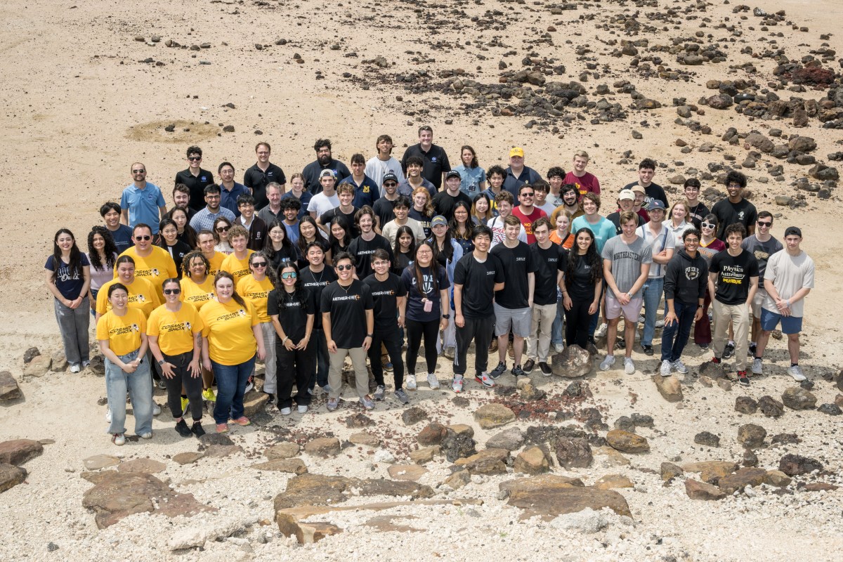
Test week at The Lyndon B. Johnson Space Center is the culmination of your teams effort and a chance to test and highlight your work to NASA team members. During the week, you should expect two sessions to showcase your work in a complete scenario. They will be spaced apart on separate days to allow additional time for fixing any issues that arise during your first session. A list of the procedures and expected timing (subject to change) that will be tested can be found here.
The rock yard is a physical location on-site at Johnson Space Center where your work will be tested. This is the same location used for several ongoing projects at NASA to validate equipment for lunar rovers and other devices. We have provided 3D scans of the rock yard which can be found here, they might be useful for development, or just to see the environment that testing will take place in.

During test week, we will be hosting an official instance of TSS. This will be deployed on a local network and you will connect to it via a network address. Provided that you are connected to the same Wi-Fi network as the server, you should be able to connect and issue commands in the exact same way. You should expect and plan that the network address for the server will differ from your development instances, so we suggest making it easy to change in your interface or code.
Teams will be assigned a specific time slot, and will test their work in that order. A typical test session will accommodate both a rover and a EVA team. Within a 45 minute test window, each team will have 5 minutes of setup and clean up, allotting 25 minutes to test their work, and a 10 minute buffer. A detailed timeline/procedure of what will be tested can be found here.
If this README or the additional documents provided in the documents folder are not enough to answer a specific question, please reach the SUITS tech team at nasa-suits@mail.nasa.gov.
If there are any notable bugs with TSS blocking development, we welcome you to create a new issue within the GitHub repository.
If you have reached the very end of this document and still want to learn more about how TSS works, feel free to read the more technical documentation located in the src folder: TSS Development Documentation